 |
| CP1H PLC by Omron |
Before going any further about how to do wiring on the CP1H PLC, the following will be explained about the parts or structures of this PLC:
 |
| Parts of Omron CP1H |
- Battery covers, location of backup battery
- Operation indicators, power, err/alarm, BKUP, RUN, INH, PRPHL.
- Peripheral USB Port, connecting PC for CX Programmer both monitoring and programming.
- 7-segmen display, 2 digits of 7 segmen shows CPU status such as error and codes.
- Analog Adjuster, adjusting value of A642 in range 0 to 256.
- External analog setting input connector, adjusting of value A642 by external input voltage 0 to 10 Volt.
- Dip switch, used for PLC setting, such as memory program protection, transfer data from memory cassete, serial communication setting, A395 status.
- Analog input terminal block and base(XA cpu only).
- Analog input switch(XA cpu only) to determine of voltage or current used on analog input.
- Slot for memory cassette CP1W-ME05M.
- Power supply, ground and input terminal block.
- Option board slots, two slots for option boards such as RS232C, RS422A/485, LCD, and ethernet.
- Input indicator.
- Expansion I/O connector.
- Output indicators.
- External power supply and output terminal block.
- Connector for CJ unit adapter.
Power Supply Connection
If viewed from supply of power, there are two types of CP1H CPU. AC type and DC type. CP1H-X40DR-A is example of AC type which supply of voltage 100 to 240 VAC. And the example of DC type is CP1H-X40DR-D with 24 DC 24 Volt. A and D which distinguish these type. The following figures are the example of about how for connecting the supply of power:
Input device connection
There are several models of the connection between input device and the PLC input circuit. Basically can be devided as follows:
In its application, the selection of a PLC output relay or transistor really considered. Some considerations can be a type of load. It is recommended to use external relay so that the internal relay of PLC unencumbered directly. As for load that require a faster response would be better to use the transistor output.
In addition, output relay also has a weakness for relay contact having a shorter life time.
- Omron CP1H with Power supply AC 100~240 Volt
 |
| CP1H wiring of AC power supply |
- Omron CP1H with Power supply DC 24 Volt
 |
| CP1H wiring of DC power supply |
Input device connection
There are several models of the connection between input device and the PLC input circuit. Basically can be devided as follows:
- NPN type, Simply be explained, that for NPN type is if the input device used is negative voltage (0 Volt of 24 Volt DC), and the common terminal of PLC input circuit is connected to positive (+24 Volt DC).
- PNP type, This is in contrast with NPN type that the input device used is positive voltage (+24 Volt DC), and the common terminal of PLC input circuit is connected to negative voltage (0 Volt of 24 Volt DC).
Selection method connection between NPN and PNP models is depend on the input device. For example, there are two types of sensor model, NPN and PNP. In addition to these considerations, sometimes there are also concerned with style and safety considerations.The following figures are several models of connection between input device and PLC input circuit:
1. Input device is contact, example relay, switch, push button

2. Input device is 2 wire
 3. Input device NPN open-collector
 4. Input device NPN current output
 5. Input device PNP current output
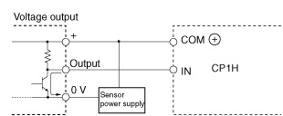
 6. Input device voltage output
 Output device connection
There are two models of PLC output circuit :
1. Output relay
There are two models of PLC output circuit :
1. Output relay
PLC with this output has relay output to drive the load. And the load will be driven by the contact relay. Of course it can drive the load with DC and AC voltage. Similarly, variations can be made with how to connect the common terminal on output circuit. Below is the figures about the output circuit connection model:
 |
| PLC output relay connection |
2. Output Transistor.
For the PLC with transistor output, there are two ways to arrange output device. This is determined by the DC voltage that connected to common. If common is connected to positive called as " Sourching transistor output", and if common is connected to negative called as "Sinking transistor output". That can be clarified with the figures below:
| Sourching Transistor Output |
| Sinking Transistor Output |
In addition, output relay also has a weakness for relay contact having a shorter life time.
But not all five languages are supported on all PLCs inexpensive PLCs comparable through those from AutomationDirect and the older PLC equivalent because the Allen Bradley SLC - 500. programmable logic controller
ReplyDelete